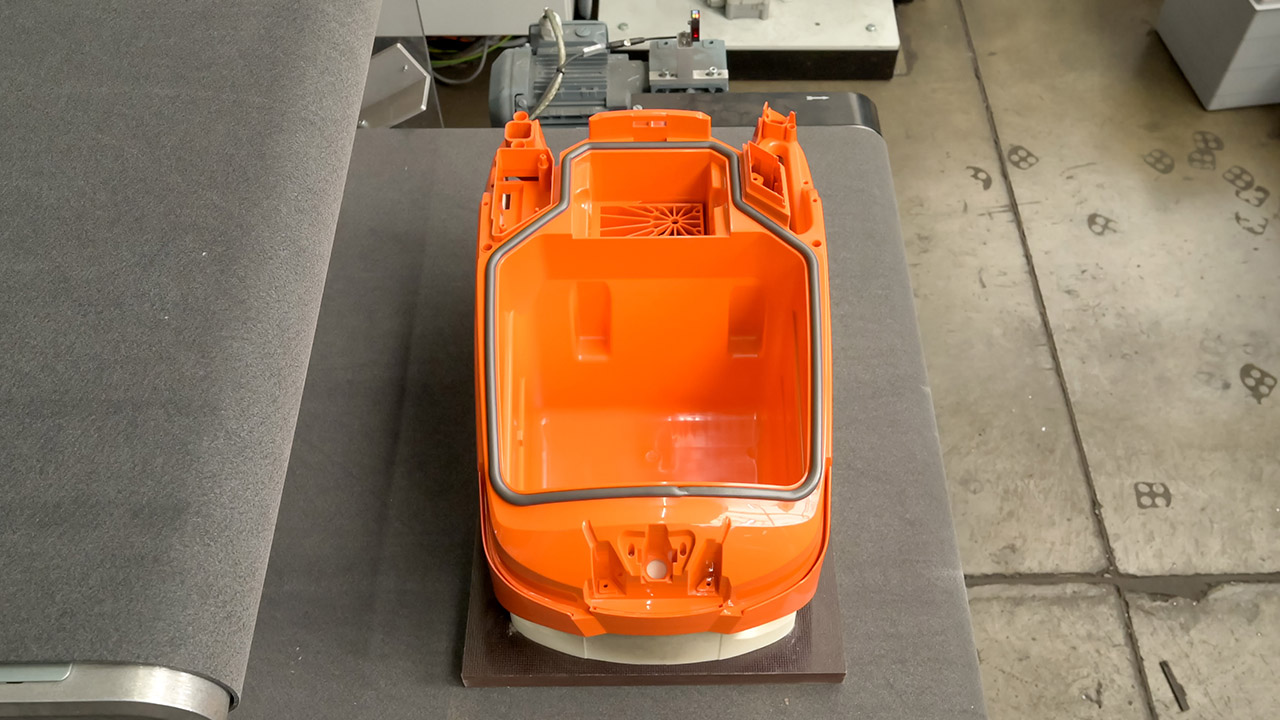
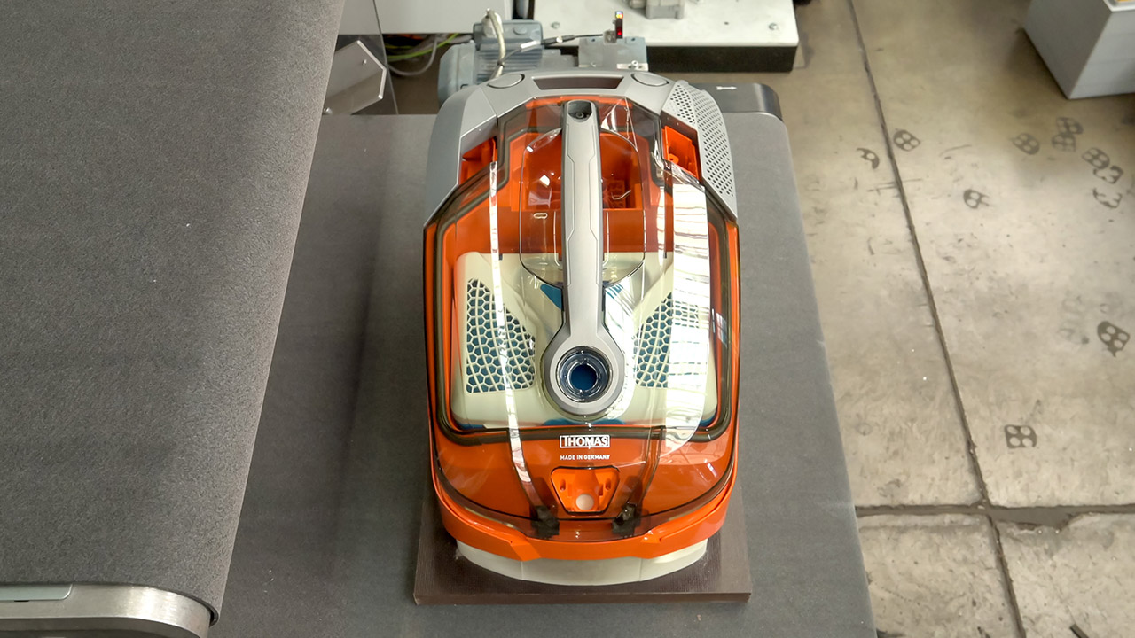
Customized sealing solutions for vacuum cleaner housings
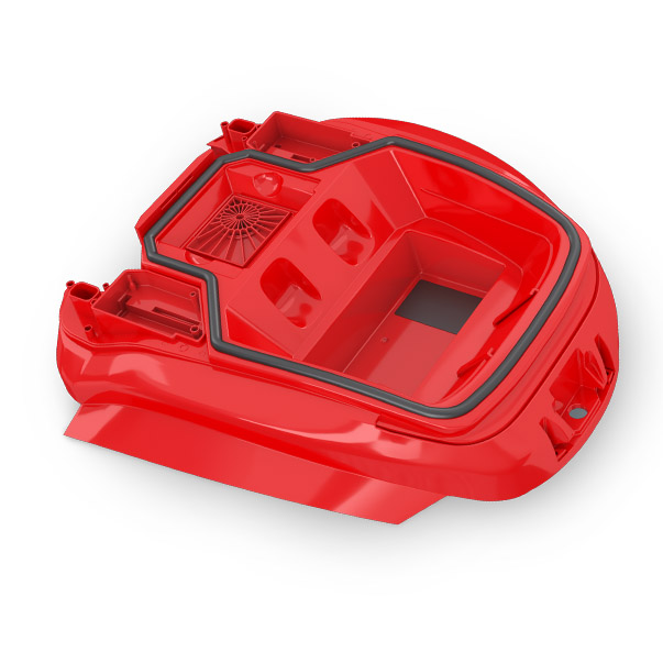
Contour-accurate and seamless sealing of vacuum cleaner housings with polyurethane foam
The reference material presented here, FERMAPOR K31-A-9025-2-VP2 and B-4 (B component), is a room-temperature curing 2- component polyurethane foam for sealing vacuum cleaner housings.
The polyurethane sealing foam has already proven itself in use by leading appliance manufacturers for many years. It is applied directly to the component using FIPFG (Formed-In-Place-Foam-Gasket) technology and our fully automated dosing machines, very precisely, safely and efficiently.
Due to the chemical reaction of the FERMAPOR K31 material components, good adhesion to the component is usually achieved.
Customized sealing solutions for vacuum cleaners
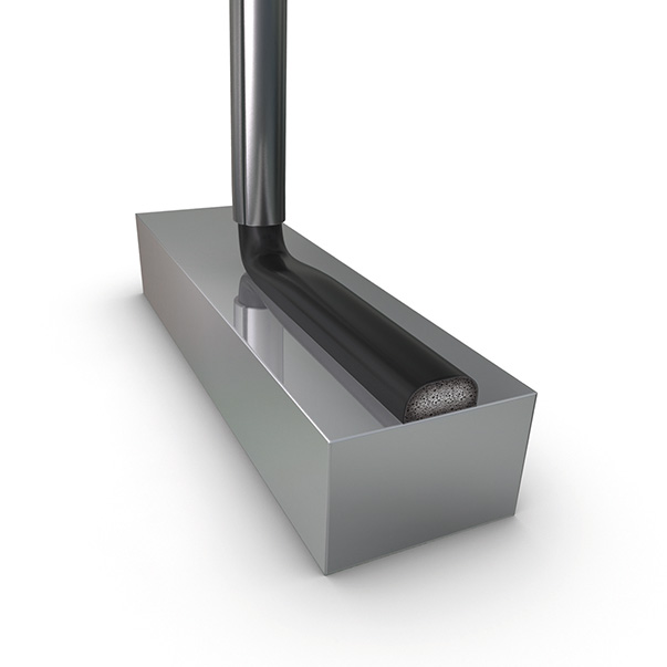
Alternatively, we can also adapt our FERMAPOR K31 polyurethane sealing foams to your specific requirements.
Influencing factors include pot life until start of foaming, curing time, and the viscosity, hardness and adhesion properties. Thanks to a mixed-cell foam structure, the closing forces when installing the foam gasket are low.
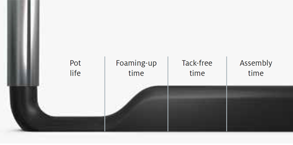
The different reaction phases of the sealing foam in the chronological sequence
Reference material
| FERMAPOR K31-A-9025-2-VP2 | ||
| FERMAPOR K31-B-4 | ||
| Mixing ratio | 4.5 : 1 | |
| Pot life time | 33 sec. | |
| Tack-free time | 5 min. | |
|
Viscosity of the A component |
44,000 mPas | |
| Density of the foam | 0.2 g/cm³ | |
| Hardness (Shore 00) | 35 | |
| Temperature resistance | from -40 to + 80 °C | |
| Pretreatment | Plasma, Corona, Primer |
In addition to the reference products, we develop material systems according to your individual requirements. Influencing factors include pot life until start of foaming, curing time, and the viscosity, hardness and adhesion properties.
Repeated opening and reclosing of housing flap with constant sealing effect
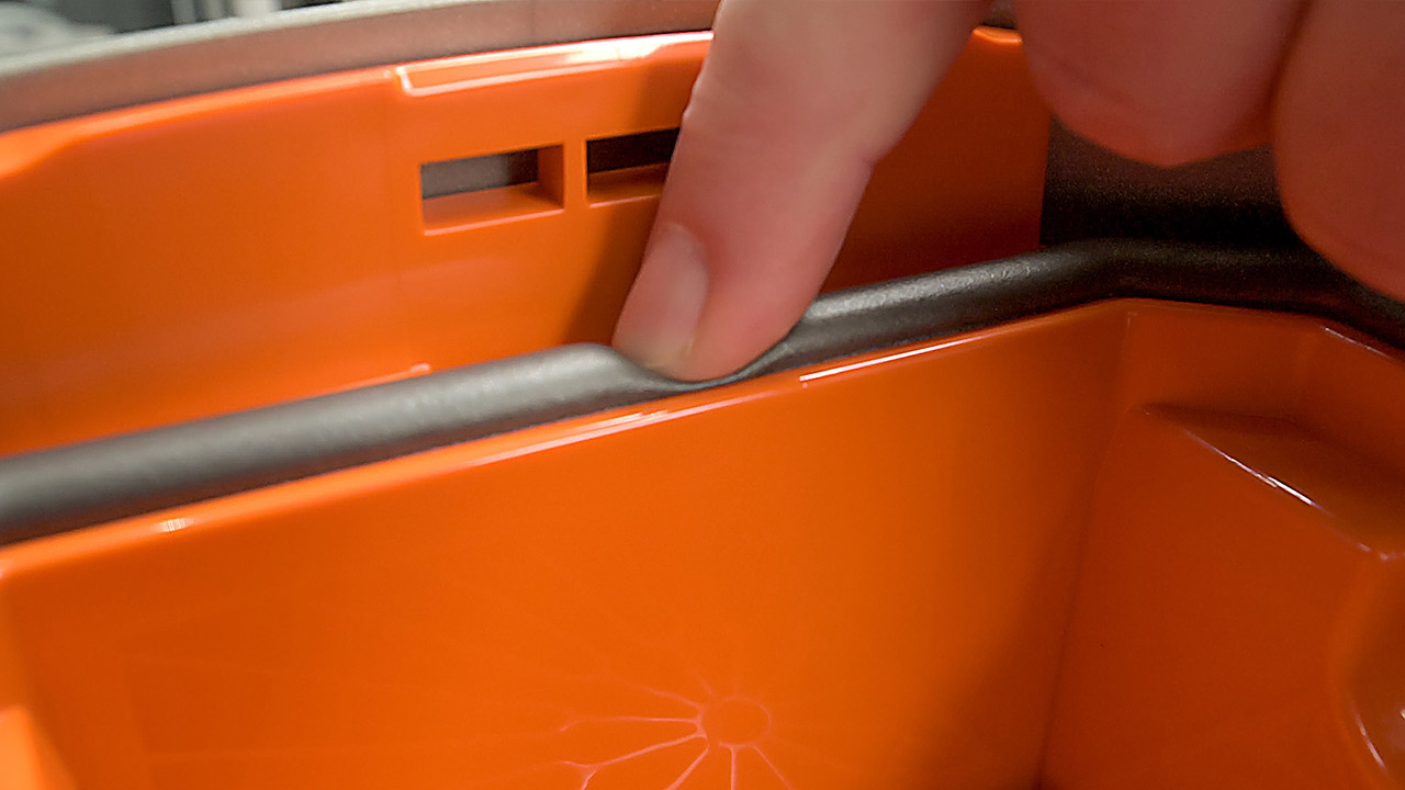
The FERMAPOR K31 foam gasket compensates for component tolerances during sealing. It has excellent long-term behavior and good shape recovery characteristics of the compressed foam after releasing the gasket, even after years.
This allows frequent opening and re-closing of the housing flap to change the dust bag while maintaining the sealing effect of the foam gasket.
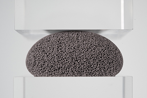
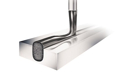
Cross-section of a polyurethane foam bead – unpressed
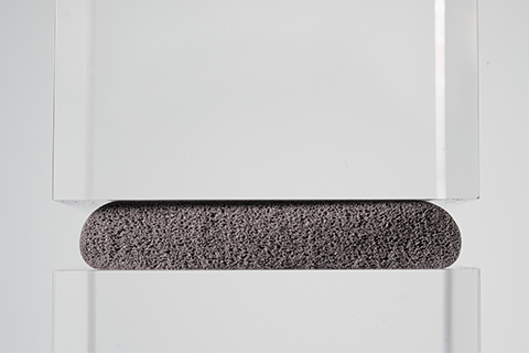
Cross-section of a polyurethane foam bead with approx. 50 % compression
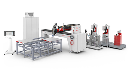
DM 502 mixing and dosing system with 3-axis linear robot for sealing vacuum cleaner housings with polyurethane foam
Flexible and fully automatic – fully in line with your requirements
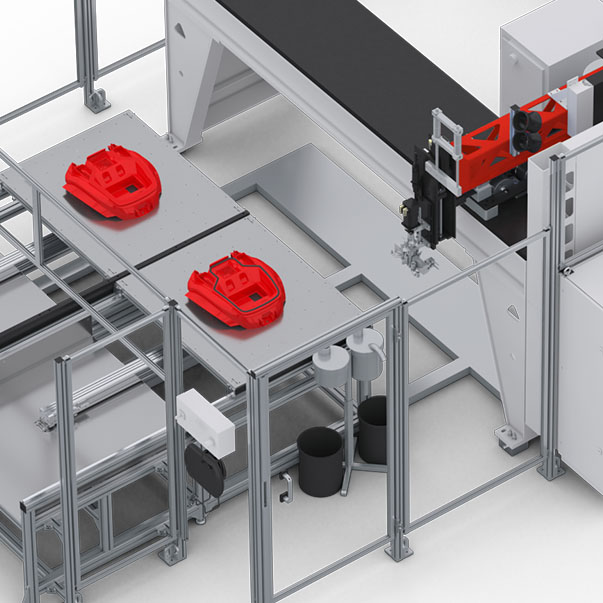
The reference configuration shown here for true-to-contour application of FERMAPOR K31 2-component polyurethane sealing foam in the groove contour of the vacuum cleaner housing consists of the DM 502 mixing and dosing system with the LR-HD 3-axis linear robot and the WT 1-LEVEL shuttle table. Parts are picked up and processed in continuous shuttle mode in one plane.
The refilling stations of the modular DM 502 system periphery are used for material-specific preparation of the implemented material systems – without contamination by the products to be filled. Equipping the refilling station with a pneumatic lift for the agitator offers more operating convenience and higher occupational and system safety. In addition, agitators stir the materials so that their consistency is homogeneous before they are put into service.
A fully automatic production process is only possible if the material pressure tanks are continuously supplied with material by the refilling stations. Capacitive sensors on the material pressure vessels monitor the filling level and control the refilling process. This means that the production process is not interrupted in the event of a material change.
The highly dynamic LR-HD 3-axis linear robot or alternatively the highly efficient LR-HE plus are responsible for the very precise and repeatable guidance of the MK 800 PRO precision mixing head over the component. The mixing head automatically applies the polyurethane foam to the pre-programmed contour with a high degree of accuracy in terms of dosing and repetition.
After the dosing cycle, the coupling point of the foam gasket closes seamlessly and is therefore almost invisible. The applied material foams, expanding to several times its original volume, and forms an elastic soft foam gasket with the desired foam hardness at room temperature.
As process experts, we support you with tailored advice for the automation of your manufacturing processes. In all solutions, our main focus is on extremely reliable plant engineering, minimized maintenance times and consistent dosing quality.
Thanks to the automatic logging of dosing program data, all process data can be traced and evaluated by the machine operator via the CONTROL 2 operating panel while production is running.
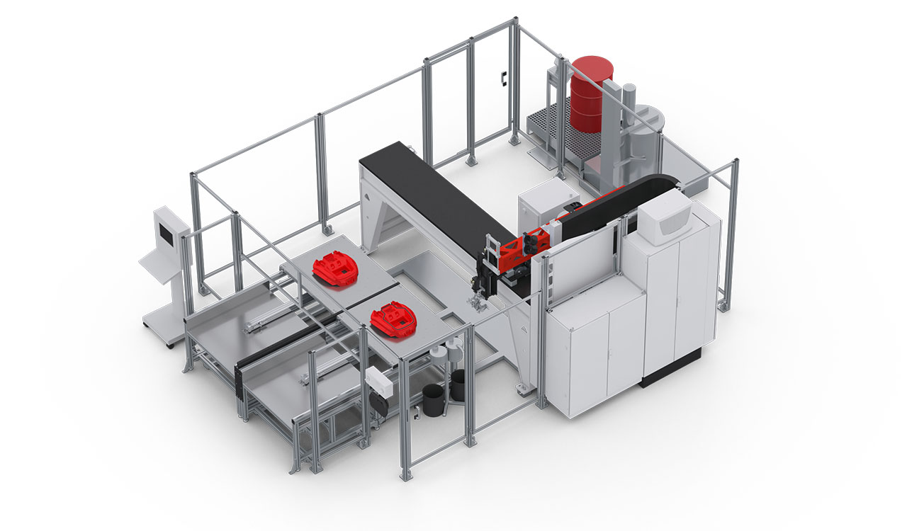 CONTROL 2
WT 1-LEVEL shuttle / sliding table
Mixing head 825 PRO
Dosing machine cabinet
Control cabinet
MP 2 Mobile panel
Supply Tap
Elevator
CONTROL 2
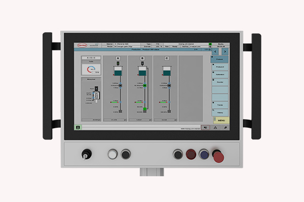
Optionally available: CONTROL touchscreen operating panel (21.5“) for operating the dosing system
More information to our operating panelsWT 1-LEVEL shuttle / sliding table
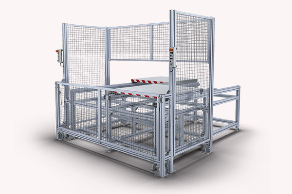
Two pick-up plates operating in pendulum mode in one plane
More information to our shuttle tablesMixing head 825 PRO
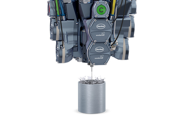
MK 800 PRO precision mixing head with high-pressure water rinsing or alternative component rinsing system
More information to our mixing headsDosing machine cabinet
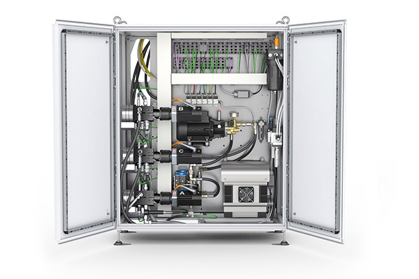
The dosing machine cabinet contains the components of the dosing periphery, e.g. the dosing pumps.
More information to our dosing machine cabinetsControl cabinet
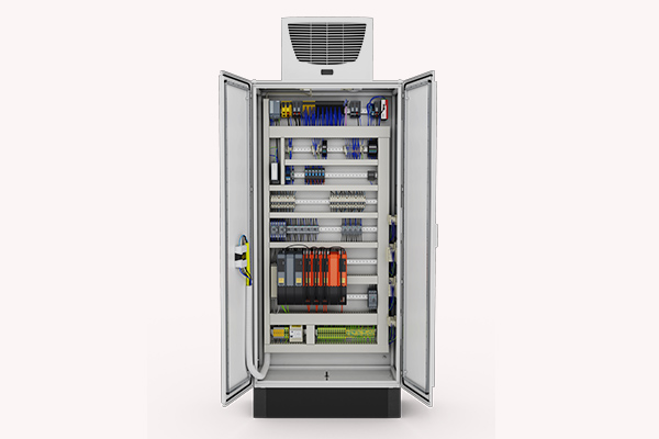
The control electronics, safety engineering and industrial PC are installed in the control cabinet.
More information to our control cabinetsMP 2 Mobile panel
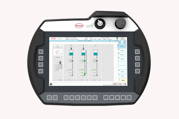
The multifunctional MP 2 mobile panel (10.1” WXGA TFT) enables convenient operation of the dosing system.
More information to our operating panelsSupply Tap
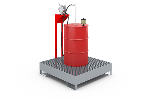
Optional: Automatic SUPPLY TAP drum refilling station for low-viscosity products, e.g. isocyanate (B-component)
More information to our refilling stationsElevator
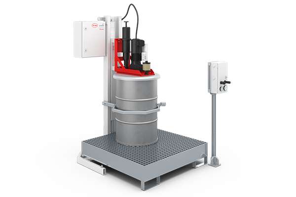
Optional: Automatic ELEVATOR drum refilling station for the A-component with pneumatic lift and agitator
More information to our refilling stationsProduction of vacuum cleaner housings of the company Thomas at Kunststofftechnik Krug GmbH
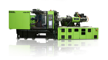
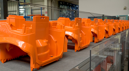
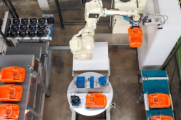
The production of vacuum cleaner housings of the company Thomas, incl. application of the Sonderhoff polyurethane foam gasket FERMAPOR K31 by Henkel on the contour of the vacuum cleaner housing and of the cover for the electric motor, takes place on an area of approx. 120 sqm and consists among others of the following plants and components:
Video of injection molding and foam gasketing of vacuum cleaners
Extended video version of injection molding and foam gasketing of Thomas vacuum cleaner and motor cover housings.
Fully automated production process using an Engel injection molding machine and SONDERHOFF DM 502.
Video of injection molding and foam gasketing of vacuum cleaners - short version
Short video version of injection molding and foam gasketing of Thomas vacuum cleaner and motor cover housings.
Fully automated production process using an Engel injection molding machine and SONDERHOFF DM 502.
Process sequence of the production of the vacuum cleaner housing as well as the gasket application for housing and motor pot:
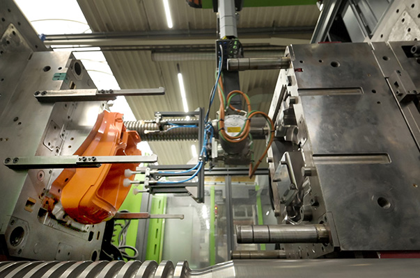
The vacuum cleaner housing made of plastic is produced by the Krug company with the Duo 650 injection molding machine from Engel in a 1-cavity mold in a 60-second cycle. The injection molding production specifies the cycle for the further process steps.
1. Removal from the mold of the injection molding machine
2. Deposit on the transfer belt
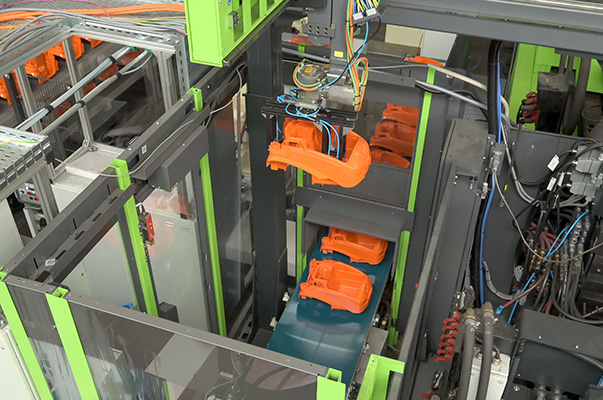
3. Clocking of the vacuum cleaner housing into the transfer position
4. Parts pick up of motor pot
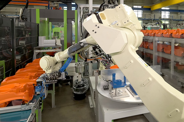
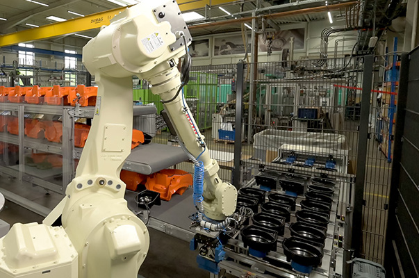
5. Parts pick up vacuum cleaner housing
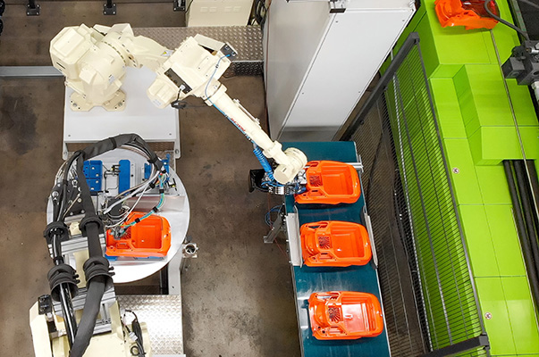
6. Deposit rotary indexing table for dosing application
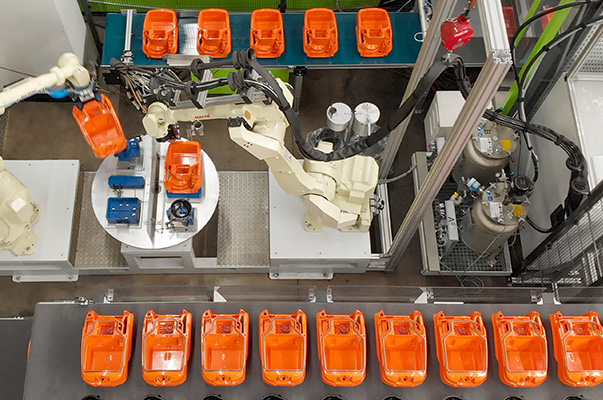
7. Dosing application on vacuum cleaner housing and motor pot
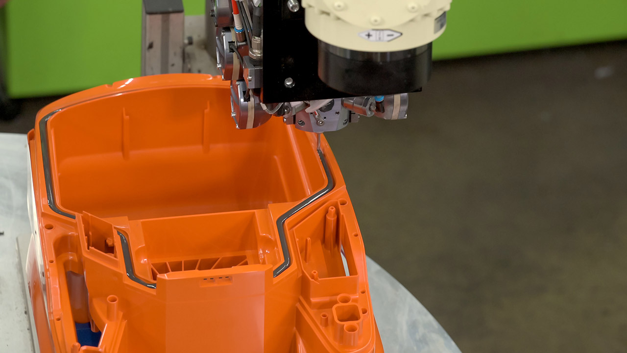
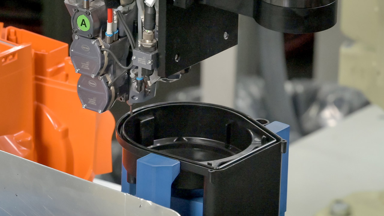
8. Turning of rotary indexing table
9. Parts removal from rotary indexing table
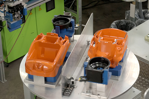
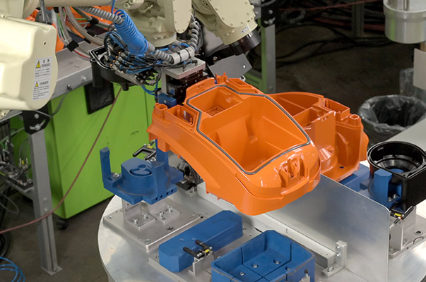
10. Quality control
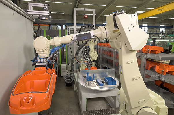
The components are guided under a camera for quality control (gasket present yes/no)
11. Deposit on the unloading belt
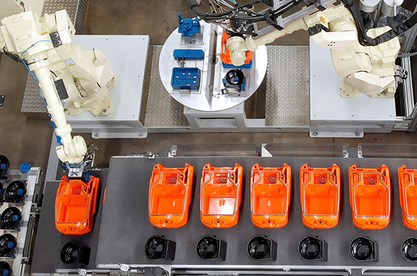
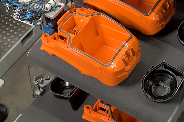
The 6-axis robot places the finished sealed parts on the unloading conveyor belt
12. Parts assembly
